操作系统 uCore Lab 1 含 Challenge
练习1:理解通过make生成执行文件的过程
- 操作系统镜像文件ucore.img是如何一步一步生成的?
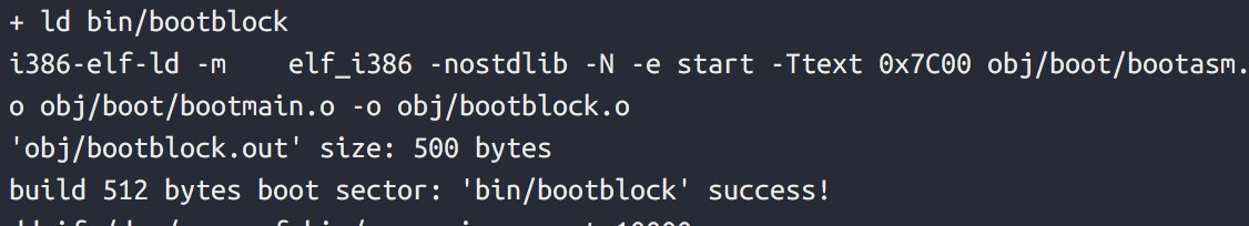
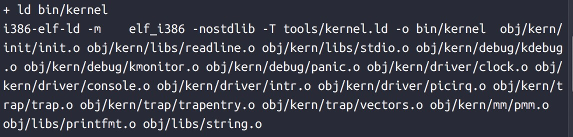
1 | $(UCOREIMG): $(kernel) $(bootblock) |
生成 Bootblock
1 | bootfiles = $(call listf_cc,boot) |
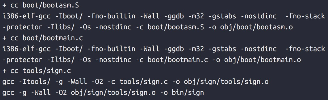
生成 Kernel
1 | KOBJS = $(call read_packet,kernel libs) |
- -ggdb 生成可供gdb使用的调试信息
- -m32 生成适用于32位环境的代码
- -gstabs 生成stabs格式的调试信息
- -nostdinc 不使用标准库
- -fno-stack-protector 不生成用于检测缓冲区溢出的代码
- -Os 为减小代码大小而进行优化
- -I添加搜索头文件的路径
- -fno-builtin 不进行builtin函数的优化
- -m 模拟为i386上的连接器
- -N 设置代码段和数据段均可读写
- -e 指定入口
- -Ttext 指定代码段开始位置
- 一个被系统认为是符合规范的硬盘主引导扇区的特征是什么?
1 | 在 tools/sign.c 里面 有以下两句 说明 符合规范的硬盘主引导扇区特征是 最后两个字节 为 0x55 0xAA 同时 主引导扇区的大小应为 512 字节 |
练习2:使用qemu执行并调试lab1中的软件
- 从CPU加电后执行的第一条指令开始,单步跟踪BIOS的执行。
- 在初始化位置0x7c00设置实地址断点,测试断点正常。
- 从0x7c00开始跟踪代码运行,将单步跟踪反汇编得到的代码与bootasm.S和 bootblock.asm进行比较。
- 自己找一个bootloader或内核中的代码位置,设置断点并进行测试。
在一个终端中先执行
1 | qemu-system-i386 -S -s -d in_asm -D bin/q.log -monitor stdio -hda bin/ucore.img |
后在另一个终端执行
1 | i386-elf-gdb |
练习3:分析bootloader进入保护模式的过程
BIOS将通过读取硬盘主引导扇区到内存,并转跳到对应内存中的位置执行bootloader。请分析bootloader是如何完成从实模式进入保护模式的。
1 | #include <asm.h> |
- 为何开启A20,以及如何开启A20
1 | 实模式下内存访问采取的 段基址:段内偏移地址 的形式 段基址要左移4位再加上段内偏移地址来访问 实模式下寄存器都是16位的 如果段基址和段内便宜地址都为16位的最大值 0xFFFF:0xFFFF 即 0x10FFEF 当实模式下的地址总线为20位 最大寻址空间为 2的20次方= 1M 的内存 超出了 1M的内存 若不打开 A20地址线 CPU将采用 8086/8088 的地址回绕 |
- 如何初始化GDT表
1 | 先提前创建好 GDT 里面的 代码段选择子 数据段选择子 然后 通过 调用 lgdt 将 GDT的界限和内存起始地址存入 GDTR 寄存器中 |
- 如何使能和进入保护模式
1 | 将 cr0 控制寄存器的 第0位 PE位 置1 |
练习4:分析bootloader加载ELF格式的OS的过程
通过阅读bootmain.c,了解bootloader如何加载ELF文件。通过分析源代码和通过qemu来运行并调试bootloader&OS,
1 |
|
- bootloader如何读取硬盘扇区的?
- bootloader是如何加载ELF格式的OS?
首先 bootloader 调用 bootmain 函数 然后读取第一个扇区的内容 到 0x10000 地址处 读取硬盘扇区的过程
0x1F2 写入扇区数
0x1F3 LBA 0715
0x1F4 LBA 8
0x1F5 LBA 16234位为1110 表示LBA模式 24~27
0x1F6 LBA 7
0x1F7 0x20 读命令
一次从 0x1F0 读入 2个字 4个字节 读入512字节 需要 128次
然后 判断 他的魔数是否为 ELF文件 若不是 则走向死循环 若是 则读 ELF 文件的程序段 到 该段的起始虚拟地址中去
练习5:实现函数调用堆栈跟踪函数
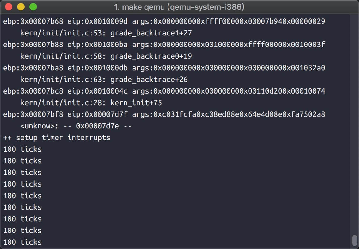
我们需要在lab1中完成kdebug.c中函数print_stackframe的实现,可以通过函数print_stackframe来跟踪函数调用堆栈中记录的返回地址。在如果能够正确实现此函数,可在lab1中执行 “make qemu”后,在qemu模拟器中得到类似如下的输出
1 | void print_stackframe(void) { |
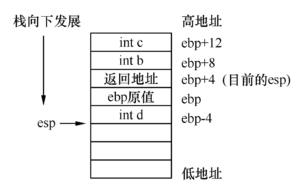
esp 栈顶指针
ebp 栈底指针
eip 寄存器存放的CPU下一条指令的地址
首先读取 ebp 和 eip 的值 然后 在ebp的地址上 + 2 就是第一个参数的位置
练习6:完善中断初始化和处理
请完成编码工作和回答如下问题:
- 中断描述符表(也可简称为保护模式下的中断向量表)中一个表项占多少字节?其中哪几位代表中断处理代码的入口?
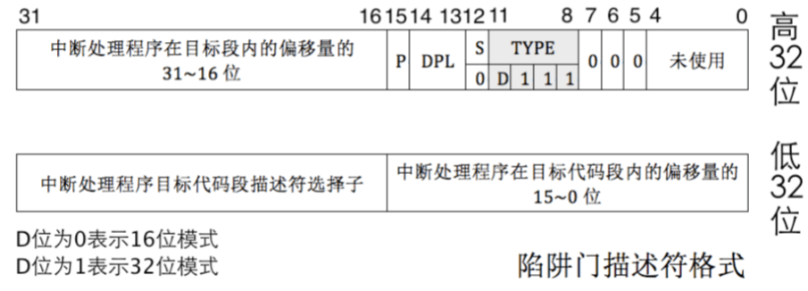
1 | /* Gate descriptors for interrupts and traps */ |
- 请编程完善kern/trap/trap.c中对中断向量表进行初始化的函数idt_init。在idt_init函数中,依次对所有中断入口进行初始化。使用mmu.h中的SETGATE宏,填充idt数组内容。每个中断的入口由tools/vectors.c生成,使用trap.c中声明的vectors数组即可。
1 | extern uintptr_t __vectors[]; |
- 请编程完善trap.c中的中断处理函数trap,在对时钟中断进行处理的部分填写trap函数中处理时钟中断的部分,使操作系统每遇到100次时钟中断后,调用print_ticks子程序,向屏幕上打印一行文字”100 ticks”。
1 | kern/trap/trap.c 138: |
扩展练习
扩展练习 Challenge 1
扩展proj4,增加syscall功能,即增加一用户态函数(可执行一特定系统调用:获得时钟计数值),当内核初始完毕后,可从内核态返回到用户态的函数,而用户态的函数又通过系统调用得到内核态的服务。需写出详细的设计和分析报告。完成出色的可获得适当加分。
1 | kern/init/init.c |
1 | kern/trap/trap.c : |
根据这张图 可以看出 内核态和用户态的转换 首先是留下 SS 和 ESP 的位置 然后 调用中断 改中断栈里面的内容 最后退出中断的时候 跳到内核态中 最后将 ebp 赋给 esp 修复 esp 的位置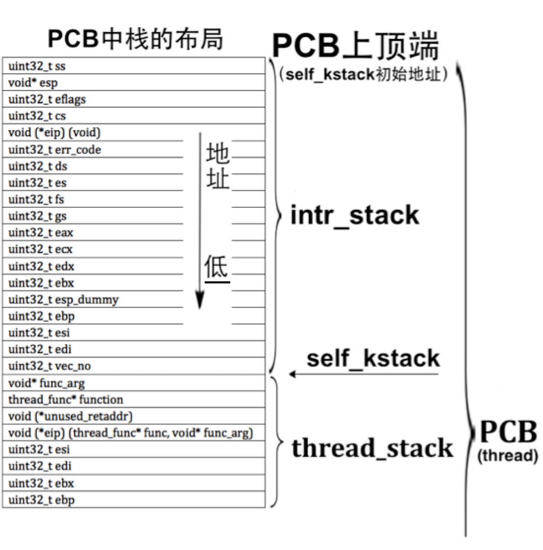
扩展练习 Challenge 2
用键盘实现用户模式内核模式切换。具体目标是:“键盘输入3时切换到用户模式,键盘输入0时切换到内核模式”。 基本思路是借鉴软中断(syscall功能)的代码,并且把trap.c中软中断处理的设置语句拿过来。
1 | kern/trap/trap.c |
按键的中断在 IRQ_KBD 处